- 您现在的位置:买卖IC网 > Sheet目录331 > IPTR-DSPBUILDER (Altera)DSP BUILDER SOFTWARE
4–6
Chapter 4: Using MegaCore Functions
MegaCore Function Design Example
Adding Stimulus and Scope Blocks
To create a sample design to test the low-pass filter by feeding the filter two sine
waves ( Figure 4–4 on page 4–8 ), follow these steps:
1. Add two Sine Wave blocks (from the Simulink Sources library).
1
DSP Builder automatically gives the second block a unique name.
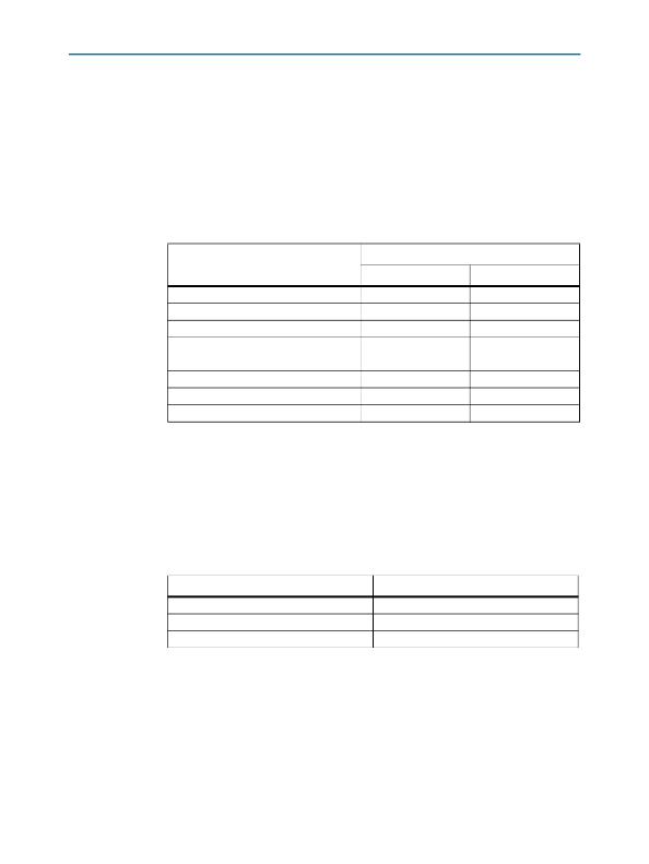
2. Use the Block Parameters dialog box to set the parameters for the Sine Wave block
( Table 4–1 ).
Table 4–1. Parameters for the Sine Wave Blocks
Value
Parameter
Sine Wave
Sine Wave1
Sine type
Time
Amplitude
Bias
Samples per period
Number of offset examples
Sample time
Interpret vector parameters as 1-D
Sample based
Use simulation time
64
0
200
0
1
On
Sample based
Use simulation time
64
0
7
0
1
On
3. Repeat Step 2 for the Sine Wave1 block.
4. Connect the outputs from the Sine Wave and Sine Wave1 blocks to an Add block
(from the Simulink Math Operations library).
5. Add an Input block (from the IO & Bus library in the Altera DSP Builder
Blockset ) and connect it between the Add block and the ast_sink_data pin on the
my_fir_compiler block.
6. Use the Block Parameters dialog box to set the parameters ( Table 4–2 ).
Table 4–2. Parameters for the Input Block
Parameter
Bus Type
[number of bits].[]
Specify Clock
Value
Signed Integer
8
Off
7. Add a Constant block (from the IO & Bus library) and connect this block to both
the ast_sink_valid and ast_source_ready pins on the my_fir_compiler block.
8. Add another Constant block (from the IO & Bus library) and connect this block to
the ast_sink_error pin on the my_fir_compiler block.
DSP Builder Handbook
Volume 2: DSP Builder Standard Blockset
November 2013 Altera Corporation
发布紧急采购,3分钟左右您将得到回复。
相关PDF资料
IR11662SPBF
IC CNTROL SMART RECTIFIER 8-SOIC
IR1166STRPBF
IC MOSFET DRIVER N-CH 200V 8SOIC
IR11672ASPBF
IC MOSFET DRIVER 200V 8-SOIC
IR1167ASTRPBF
IC SMART SECONDARY DRIVER 8-SOIC
IR11682STRPBF
IC MOSFET DRIVER DUAL 200V 8SOIC
IR1168SPBF
IC MOSFET DRIVER DUAL 200V 8SOIC
IR1176STR
IC DRIVER RECT SYNC 5V 4A 20SSOP
IR2010SPBF
IC DRIVER HIGH/LOW SIDE 16SOIC
相关代理商/技术参数
IP-TRIETHERNET
功能描述:开发软件 Triple Spd Ethernet MegaCore
RoHS:否 制造商:Atollic Inc. 产品:Compilers/Debuggers 用于:ARM7, ARM9, Cortex-A, Cortex-M, Cortex-R Processors
IP-TRIETHERNETF
功能描述:开发软件 3x Spd Ethernet MAC MegaCore
RoHS:否 制造商:Atollic Inc. 产品:Compilers/Debuggers 用于:ARM7, ARM9, Cortex-A, Cortex-M, Cortex-R Processors
IPTV-OPTION-INS970
制造商:3M Electronic Products Division 功能描述:IPTV OPTION FOR INS970
IPU039N03L G
功能描述:MOSFET N-CH 30V 50A 3.9mOhms RoHS:否 制造商:STMicroelectronics 晶体管极性:N-Channel 汲极/源极击穿电压:650 V 闸/源击穿电压:25 V 漏极连续电流:130 A 电阻汲极/源极 RDS(导通):0.014 Ohms 配置:Single 最大工作温度: 安装风格:Through Hole 封装 / 箱体:Max247 封装:Tube
IPU039N03LG
制造商:INFINEON 制造商全称:Infineon Technologies AG 功能描述:OptiMOS?3 Power-Transistor Features Fast switching MOSFET for SMPS
IPU039N03LGXK
制造商:Infineon Technologies AG 功能描述:Trans MOSFET N-CH 30V 50A 3-Pin(3+Tab) TO-251
IPU04N03LA
功能描述:MOSFET N-CH 25V 50A IPAK RoHS:否 类别:分离式半导体产品 >> FET - 单 系列:OptiMOS™ 标准包装:1,000 系列:MESH OVERLAY™ FET 型:MOSFET N 通道,金属氧化物 FET 特点:逻辑电平门 漏极至源极电压(Vdss):200V 电流 - 连续漏极(Id) @ 25° C:18A 开态Rds(最大)@ Id, Vgs @ 25° C:180 毫欧 @ 9A,10V Id 时的 Vgs(th)(最大):4V @ 250µA 闸电荷(Qg) @ Vgs:72nC @ 10V 输入电容 (Ciss) @ Vds:1560pF @ 25V 功率 - 最大:40W 安装类型:通孔 封装/外壳:TO-220-3 整包 供应商设备封装:TO-220FP 包装:管件
IPU04N03LA G
功能描述:MOSFET N-CH 25V 50A IPAK RoHS:是 类别:分离式半导体产品 >> FET - 单 系列:OptiMOS™ 标准包装:1,000 系列:MESH OVERLAY™ FET 型:MOSFET N 通道,金属氧化物 FET 特点:逻辑电平门 漏极至源极电压(Vdss):200V 电流 - 连续漏极(Id) @ 25° C:18A 开态Rds(最大)@ Id, Vgs @ 25° C:180 毫欧 @ 9A,10V Id 时的 Vgs(th)(最大):4V @ 250µA 闸电荷(Qg) @ Vgs:72nC @ 10V 输入电容 (Ciss) @ Vds:1560pF @ 25V 功率 - 最大:40W 安装类型:通孔 封装/外壳:TO-220-3 整包 供应商设备封装:TO-220FP 包装:管件
